Diodes are essential electronic components that allow current to flow in one direction. Testing a diode with a multimeter helps determine if it’s functioning correctly or if it’s faulty (open or shorted). Follow these steps to test a diode using a digital or analog multimeter.
Tools Required
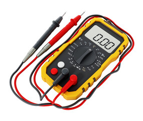
- Digital Multimeter (DMM) or Analog Multimeter
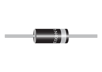
- Diode (to be tested)
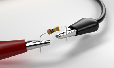
- Alligator clips or test leads (optional for better contact)
Step 1: Set the Multimeter to Diode Test Mode
- For Digital Multimeters (DMM):
- Turn the dial to the diode symbol (⎓) or “Diode Test” mode.
- If your multimeter doesn’t have a diode mode, use the resistance (Ω) mode (less accurate).
- For Analog Multimeters:
- Set the dial to the lowest resistance range (e.g., ×1Ω or ×10Ω).
Step 2: Identify the Diode’s Anode and Cathode
- A diode has two terminals:
- Anode (A, positive side) – Usually marked with a band or line.
- Cathode (K, negative side) – Unmarked side.
Step 3: Test the Diode in Forward Bias (Good Diode Should Conduct)
- Connect the multimeter leads:
- Red probe → Anode (A)
- Black probe → Cathode (K)
- Check the reading:
- Digital Multimeter (DMM):
- A good diode shows 0.5V to 0.7V (for silicon diodes) or 0.2V to 0.3V (for germanium diodes).
- If it reads “OL” (Open Loop) or “1”, the diode is open (faulty).
- Analog Multimeter:
- The needle should move toward low resistance (near 0Ω).
- If it stays at ∞ (infinity), the diode is open.
- Digital Multimeter (DMM):
Step 4: Test the Diode in Reverse Bias (Good Diode Should Block Current)
- Reverse the leads:
- Red probe → Cathode (K)
- Black probe → Anode (A)
- Check the reading:
- Digital Multimeter (DMM):
- A good diode shows “OL” (Open Loop) or “1” (no conduction).
- If it shows a voltage or low resistance, the diode is shorted (faulty).
- Analog Multimeter:
- The needle should stay at ∞ (infinity).
- If it moves toward 0Ω, the diode is shorted.
- Digital Multimeter (DMM):
Step 5: Interpret the Results
| Condition | Forward Bias Test | Reverse Bias Test | Conclusion |
|---|---|---|---|
| Good Diode | 0.5V–0.7V (Si) / 0.2V–0.3V (Ge) | OL / ∞ | Working properly |
| Open Diode (No Conduction) | OL / ∞ | OL / ∞ | Faulty (Replace) |
| Shorted Diode (Full Conduction) | Low voltage (~0V) | Low resistance (~0Ω) | Faulty (Replace) |
Additional Tips
- For LED Testing: Use the diode mode—a working LED will light up slightly.
- In-Circuit Testing: Remove the diode from the circuit for accurate results.
- Schottky Diodes: Expect a lower forward voltage (~0.2V–0.4V).
Conclusion
By following these steps, you can quickly determine if a diode is functional or faulty. A good diode conducts in one direction (forward bias) and blocks current in the other (reverse bias). If it fails either test, replace it.