Introduction
Diodes are fundamental electronic components that allow current to flow in one direction while blocking it in the opposite direction. But how does a diode work in a circuit? Whether you’re designing power supplies, signal processing circuits, or protection systems, understanding diode behavior is crucial.
In this guide, we’ll explain how diodes function in circuits, their key characteristics, different types, and practical applications.
What is a Diode?
A diode is a semiconductor device with two terminals—anode (A) and cathode (K)—that conducts current only when forward-biased.
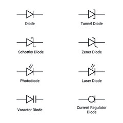
Diode Symbol & Construction
- Symbol: Arrow (anode) points toward the line (cathode).
- Material: Made of silicon (Si) or germanium (Ge) with a P-N junction.
How Does a Diode Work?
A diode operates based on biasing conditions:
1. Forward Bias (Conducting State)
- Positive voltage on anode, negative on cathode.
- Depletion region narrows, allowing current flow.
- Forward voltage drop (Vf): ~0.7V (Si) or ~0.3V (Ge).
2. Reverse Bias (Blocking State)
- Negative voltage on anode, positive on cathode.
- Depletion region widens, blocking current.
- Leakage current (very small) flows.
3. Breakdown Region (Zener & Avalanche Effect)
- If reverse voltage exceeds breakdown voltage, current flows (used in Zener diodes).
Types of Diodes & Their Functions in Circuits
Different diodes serve unique purposes:
| Type | Function | Applications |
|---|---|---|
| Rectifier Diode | Converts AC to DC | Power supplies, battery chargers |
| Zener Diode | Voltage regulation | Voltage stabilizers, surge protectors |
| Schottky Diode | Fast switching, low Vf | High-frequency circuits, SMPS |
| LED (Light Emitting Diode) | Emits light | Displays, indicators |
| Varactor Diode | Variable capacitance | RF tuning, oscillators |
Diode Applications in Circuits
Diodes are used in various electronic systems:
1. Rectification (AC to DC Conversion)
- Half-wave & Full-wave rectifiers convert AC to pulsating DC.
2. Voltage Clipping & Clamping
- Clippers limit signal amplitude.
- Clampers shift DC level of signals.
3. Reverse Polarity Protection
- Prevents damage if power supply is connected backward.
4. Signal Demodulation (AM/FM Radio)
- Extracts audio signals from carrier waves.
5. Logic Gates (Digital Circuits)
- Used in AND, OR gates in early digital circuits.
Key Diode Parameters to Consider
When selecting a diode, check:
✔ Forward Voltage Drop (Vf) – Lower = less power loss.
✔ Maximum Reverse Voltage (Vr) – Must exceed circuit voltage.
✔ Switching Speed – Critical for high-frequency circuits.
✔ Current Rating (If) – Must handle expected current.
Common Diode Circuits Explained
1. Half-Wave Rectifier
- Uses one diode to pass only the positive half-cycle of AC.
2. Full-Wave Bridge Rectifier
- Uses four diodes to convert both AC half-cycles into DC.
3. Zener Voltage Regulator
- Maintains constant output voltage despite input fluctuations.
Troubleshooting Diode Circuits
❌ No current flow?
- Check forward bias polarity.
- Measure Vf with a multimeter (~0.7V for Si).
❌ Excessive heat?
- Diode may be reverse-biased beyond breakdown.
- Verify current rating is sufficient.
Conclusion
Diodes are essential for controlling current direction in circuits. Whether in power supplies, signal processing, or protection circuits, understanding how a diode works helps in designing efficient electronics.
🔹 For rectification, use rectifier diodes.
🔹 For fast switching, choose Schottky diodes.
🔹 For voltage regulation, Zener diodes are ideal.